Fish Light
Hardware
Instead of giving the entire schematic, I would like to briefly discuss the most important segments, as the entire system is simply composed of few simple "building blocks".
Power Supply
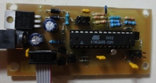
As mentioned earlier, the device needed to fit the already exiting aquarium lamp, which uses +12V DC power supply adapter. Since ATmega88 can be supplied by maximum 5.5V, I used a standard LM7805 voltage regulator.
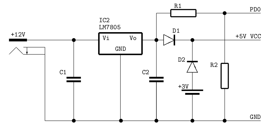
In order to transform +12V voltage supply to +5V operating voltage of the microcontroller, a common voltage regulator LM7805 is used. As usual, it is supported by two capacitors C1 and C2, whose values in this case is 22 μF. Next, to realise the promise of the "emergency" power supply a 3V battery is used. According to the datasheet, the operating voltage range for ATmega88 is 1.8 to 5.5 V, thus +3V battery backup works just fine, despite a small voltage drop across the D2 diode. The task of the D2 diode is to prevent any current flow into the battery under normal operation. Similarly, the aim of D2 is to block the current flowing through the resistors R1,2 in case of voltage drop. Finally, the resistor R1 is used to limit the current flowing into the PD0 pin and R2 is used as pull-down for the PD0 line in case of battery operation.
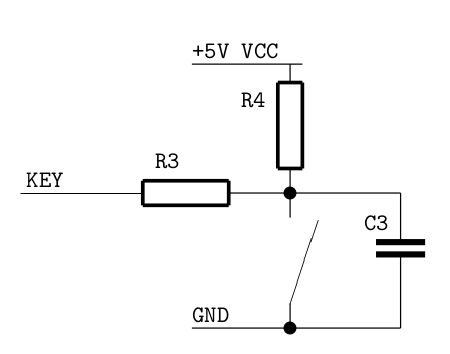
Input
ATmega88 uses two signal inputs in this case: the 32.768 kHz crystal oscillator and four push-buttons. The word KEY refers to any of the four input signals. The resistors R3,4 are used to limit the current flowing to the pin, when the button is pushed. The capacitor C3 is not mandatory, but it is used to prevent key bouncinig. The 32.768 kHz crystal is connected to TOSC1,2 pins directly without any other components' assistance.
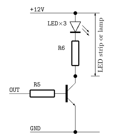
Output
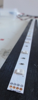
There are four output channels. Three of them (R, G, B) are connected to the LED tape, which apart from LEDs, contain the current-limitting resistors. The fourth channel is used for the lamp, which is nothing else, but set of white LEDs connected with resistors in series. Therefore, it is possible to use a similar circuit for driving each of them. Here, we use a bipolar transistor, and we need to use R5 resistor to limit the current flowing into the transistor.
Installation
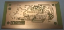
Finally, the device was packaged inside a small wooden box, in which I drilled few holes for wires and buttons. The LED strip was glued to an installation, which was made by my wife and illuminated the city-like contour. The PCB I created myself, but since I do not possess a truly repeatable recipe, I will not provide the details.